|
Beautiful, Yet Friendly Part 1: Stop Hitting the Bottleneck Beautiful, Yet Friendly Part 2: Maximizing Efficiency Beautiful, Yet Friendly Part 2: Maximizing Efficiencyby Guillaume Provost
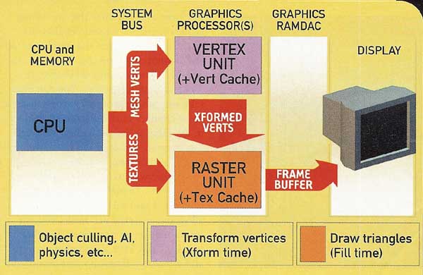
Last month, in the first part of this series on content optimization techniques, I reviewed performance at a high level and looked at how level design and environmental interactions affect it. Since most of the theory behind this month's article was also explained in the first part, I strongly suggest that readers get familiar with the concepts introduced last month before reading this article. You'll need to know when and what to optimize before you can make any use of knowing how to optimize. Last month, we saw that meshes could be transform-bound or fill-bound. I've given a more complete picture of the possibility space here through the generic hardware pipe shown in Figure 1.
If you are data-bound, then the amount of data transferred might also be causing transform problems (too many vertices) and/or fill problems (too much texture data). Data-related problems generally arise through a collection of objects, not by single objects in isolation. If you find that you're clogging the bus -- generally when there's too much texture data -- then you should redistribute your texture and vertex densities across your scene (last month's article described how to do this). If you are CPU-bound, then it's out of your hands; the programming team will need to take a hard look at their code.
If design wants marching armies of zombies attacking the player, you'll need to make sure they don't put the renderer (and artist) on death row by minimizing their transform cost. We saw last month that the cost of a transform-bound mesh is: Transform Cost = Vertex Count * Transform Complexity Hence, we need to reduce the transform complexity or the number of vertices. You can somewhat reduce the transform complexity by plucking out bones you don't really need, but you should consider using a less expensive type of transform first. If you can approximate a morph target accurately enough with a few bones, you'll save on transform complexity. If your engine is optimized for nonweighted vertex blending (where vertices can be affected by only one bone), see if you can substitute your vertex-weighted mesh with a clever distribution of bones that take no vertex weights. In any case, take the time to consult with the programmers, as they may have insights on better transform techniques you can use to lower your transform complexity. Before you go plucking vertices out of your mesh, I'll let you in on a secret: the vertex counts in your typical modeling package don't reflect reality. As they travel down the pipeline, vertices get split and resplit ad nauseam. Vertex splits adversely affect transform-bound meshes by adding spatially redundant vertices to transform. In theory, vertices can get split as many times as they touch triangles, but in practice, total vertex counts generally double or triple. Keeping this in mind, you can lower this split ratio dramatically and make your mesh a whole lot more performance-friendly without removing a single vertex. Let's first examine the nature of the splits. As I mentioned last month, graphics hardware thinks in terms of surfaces, not objects (that is, the set of all faces in an object that share the same material properties). So the first vertices that get split are those lying on the boundaries of two different surfaces. Think of it in your head as: A vertex cannot be shared across multiple materials (Figure 2b).
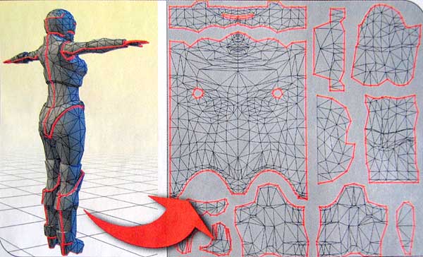
Similarly, renderers typically do not allow vertices to share polygons with different smoothing groups, or vertices that have different UV coordinates for different triangles. So vertices that lie on the boundaries of two different smoothing groups are split, and vertices that have multiple UV coordinates (which lie on the boundaries of discontinuities in UV space) will also cause splits (Figures 2c and 2d). Moreover, if you have objects with multiple UV channels, the splits will occur successively through every channel. There are several simple ways to minimize individual types of splits. Intelligently combining and stitching textures together, for example, can help minimize material-based splits. UV space discontinuities tend to be a bit trickier. Mapping an element without any UV break means that you'll have to find either an axis of symmetry or at the very least a "wrapping point" on your mesh. If you can get away with using mapping generators, such as planar, cylindrical, or cubic mappings, you can minimize or altogether eliminate UV space discontinuities. Ball-jointed hips and shoulders, for example, can make the resulting arm and leg elements ideal candidates for such techniques. If you need to split the mesh in UV space, both 3ds Max 5 and Maya have elaborate UV-mapping tools that permit you to stitch UV seams in order to minimize the damage (Maya even has a UV- space vertex counter, which should reflect the number of vertices in your mesh after UV splits.). It's generally well worth spending the time to optimize your mapping in UV space, since it will also both simplify your texturing pass and minimize the texture space you will actually need for the object. When no axis of symmetry existed, we found that treating the texture as pieces of cloth that you "sew" up worked well to minimize UV splits when texturing humanoids (Figure 3).
If you are building a performance-practical mesh, it's probably best that you fine-tune and optimize the smoothing groups by hand. Remember that the goal isn't to minimize the number of different smoothing groups, but rather the number of boundaries that separate those smoothing groups. You can also fake smoothing groups by using discrete color changes in the texture applied to it, avoiding splits altogether, although this may not result in the visual quality you are attempting to achieve. Another way to look at it in the big picture is to "reuse" vertex splits. For example, I said earlier that renderers allow one material per vertex and one smoothing group per vertex. In other words, if you have a smoothing group and a material ID group that occupy the same set of faces, they'll get split only once. The same goes for UV discontinuities: if they occur at smoothing group boundaries, then they won't cause an extra split to occur. For the record, if your mesh is definitely transform-bound, then it is generally more important for you to save on vertex splits than to save on texture memory. If that means authoring an extra texture for the mesh in order to get rid of individual diffuse color-based materials or UV breaks, then it's a fair trade-off. This brings us to normal maps and the general (and increasingly popular) concept of using high-detail meshes to render out game content. Normal maps are textures for which every texel represents a normal instead of a color. Since they give extremely fine control over the shading of a mesh, you can replicate smoothing groups and add a whole lot of extra shading detail by using them. Since normal maps are generally mapped using the same UV coordinate set as the existing diffuse texture, they do not cause extra vertex splits to occur, and are in effect cheaper for transform-bound meshes -- and much better looking -- than smoothing groups. Unfortunately, normal maps cannot really be drawn by hand; they require specialized tools to generate them, and also require higher-resolution detail meshes if you want to take full advantage of their potential. Because of the pixel operations involved that are required to support them, they are also not supported on all hardware platforms. Overall, absolutely try to avoid checkerboard-like material switches, where you consistently cycle between materials. Unless your programmers specifically support it, also avoid setting whole objects as flat-shaded by having individual faces each be a different smoothing group (Figure 4).
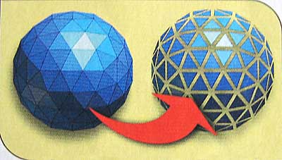
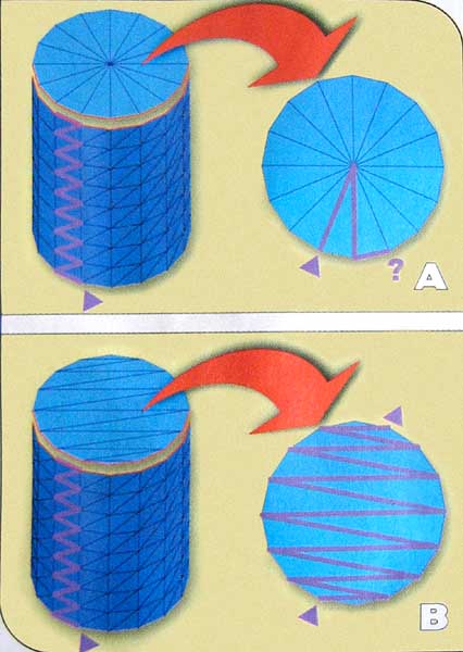
When I originally set out writing this article, I naively thought I could safely cover solid guidelines that covered all mainstream console systems and all recent PC-based graphics cards without encountering critical system-specific guidelines. I was overly optimistic. Some systems don't support indexed primitives, and some don't have a T&L transform cache. In either case, your surfaces' transform cost will be significantly affected by their "strip-friendliness." If your hardware does support both, then strip-friendliness is less of a performance issue. A triangle strip is a triangular representation some systems use in order to avoid transforming a vertex multiple times if it's shared among one or more triangles. In a triangle strip, the first three vertices form a triangle, but every successive vertex also forms a triangle with its two predecessors. When graphics processors draw these strips, they only need to transform an additional vertex per triangle, effectively sharing the transform cost of the vertices with the last (and next) triangle. Stripping algorithms close a strip (effectively increasing transform time) when there are no vertices they can choose in order to form a new triangle. This typically happens at tension points (Figure 5), where a single vertex is shared amongst a very high number (eight or more) of triangles. (Certain renderers support what are called triangle fans. Fans make tension points very efficient, but given that current hardware only supports one type of primitive per surface, they tend to rarely be supported in practice.)
Since tension points are always connected to a series of very thin triangles, avoiding sliver triangles and distributing your vertex density as equally as possible on the surface of your mesh will generally help the stripping process. Most good triangle-stripping algorithms will automatically retriangulate triangles lying on the same plane, but they cannot reorient edges binding faces on different planes. You should verify these details with the programmers.
Knowing about all these technical details can make a transform-bound mesh up to three times more efficient if you're smart about what you're doing, but it's still a lot of work. Always ask yourself whether you need to optimize a mesh before you dive into the hard work. Otherwise, use these techniques opportunistically. In the end, having a tool that helps visualize where vertex splits occur is tantamount to building truly optimized meshes. As a summary of things to look out for, here's an optimization checklist for transform-bound meshes:
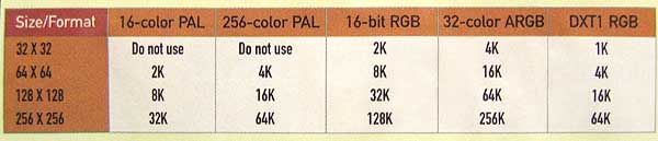
We saw earlier that the cost associated with drawing fill-bound meshes was a function of three things: Fill Cost = Pixel Coverage * Draw Complexity * Texel Density You can't make your walls any smaller than they are, but you should avoid overlaying several large surfaces within the same visibility space. A typical example of this would be to have an entire room's wall covered with an aquarium (the back wall and the glass window create two layers), or successive sky-wide layers of geometry to simulate a cloudy day. Transparent and additive geometry tend to accumulate on-screen, potentially creating several large layers of geometry the renderer needs to draw, thereby creating a fill-related bottleneck. If your export pipeline supports double-sided materials, be wary of using them arbitrarily on large surfaces; you can easily double your fill-rendering costs if you are forcing the render to draw wall segments that should be culled. On some platforms, back-face culling is not an integral part of the drawing process, and culling individual polygons becomes a very expensive task; if you are authoring content for such platforms, you should ensure that walls that don't need back faces don't have them. The bigger the triangles, the less texture space you want to address. Unfortunately, in practice, meshes that take up the largest portion of screen space also tend to also gobble up the most texture space, and so they are prime targets for being fill-related bottlenecks. There are two things you should do to minimize your texture space: make sure you are using and generating mip-maps, and choose your texture formats and size intelligently. Table 1 illustrates savings you can achieve by making smart choices about your texture formats. Note that if your textures are smaller than 32x32 texels, it's probably not a good idea to palletize them, since the cost associated with uploading and setting up the palette is larger than just using the unpalletized version. If your hardware supports native compression formats, such as DXT (DirectX Texture Compression), it's a good idea to use them over palettes.
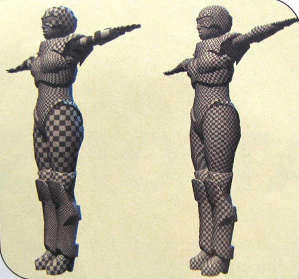
If you can get away with using diffuse colors only on a fill-bound surface, so much the better. On several platforms, drawing untextured surfaces is faster then drawing textured ones. I mentioned earlier that it was generally a fair trade-off to sacrifice texture space in order to prevent UV splits in transform-bound meshes. When your mesh is fill-bound, however, the contrary rule applies: if splitting the vertices in UV space will help you save texture space, it's also a fair trade-off. Finally, conservative decisions on the nature of the materials you apply to fill-bound meshes payoff in performance. The number of texture passes and the complexity of their material properties is always the biggest factor at play when dealing with fill-bound surfaces. Some of us deal with the creme de la creme when it comes to hardware, but the vast majority of us need to contend with market realities. In the console market, teams get to push a system to its limits, but they are also stuck with those limits for a long time. If you count yourself in that situation, then chances are you need to take something called texel cache coherency into account. Here's how it works. Graphics processors typically draw triangles by filling the linear, horizontal pixel strips that shape them up in screen- space. Almost all current hardware can do this by "stamping" several pixels at a time, greatly decreasing the time it takes to fill the triangle. For every textured pixel the card draws, it needs to retrieve a certain amount of texels from its associated texture (since the pixels are unlikely to fall directly on a texel, renderers typically set up video hardware for bilinear filtering, which fetches and blends four texels for each texture involved). It does this through a texel cache, which is basically a scratchpad on which the card can paste texture blocks. Every time the card draws a new set of pixels it looks into its cache. If the texels it needs are already present in the scratchpad, then everything proceeds without a hitch. If some texels it needs are not in the cache, then the card needs to read in new texture chunks and place them in the cache before it can proceed with drawing. This is called a texture cache miss. A good texel cache coherency means few texture cache misses occur when drawing a surface. A bad texel cache coherency will significantly increase the time it takes to draw a surface. Most PC-based systems and a few of the current high-end consoles will automatically ensure a good texel cache coherency by choosing the proper mip level at every pixel they draw. But other systems rely on the fact that the texel density across the surface area of a mesh in geometric space is constant for their mip level choice to be correct. On such systems, non-uniform texel densities will cause the card to "jump" in texture space from pixel to pixel. This can cause severe texture aliasing problems and will also consistently cause texture cache misses to occur as the card tries to fetch texels that are not in its scratchpad. As an artist, you can solve both those visual artifacts and performance problems by ensuring you uniformly distribute texel density across your mesh (Figure 6). You can do this by ensuring that the size and shape of your faces in UV space is roughly proportional to their counterparts in geometrical space. This is a concept that makes sense from an artistic perspective as well: if a face is bigger, it should get more texture detail (a larger UV space coverage) than a smaller one.
The concept extends to objects too: if an object is smaller, it's likely to be smaller on-screen as well, and should get a smaller (less detailed) texture. Following is a list of things to do and look out for when constructing fill-bound geometry:
The good news about fill-bound surfaces is that, although adding more vertices probably won't help, it probably won't make much of an impact until your vertex density is high enough for your mesh to become transform-bound. (However, very large polygons can on some systems trash the texture cache, effectively increasing fill time. In such cases, tessellating the polygons will actually help.) If your head is spinning by now, remember Douglas Adams's motto: Don't panic. Although there is a lot more to performance-friendly content than meets the eye, building efficient content can become an intuitive, natural process with practice. Whether they are vertices, texels, objects, or textures, it's more about uniformly distributing them than about plucking out detail. This is a very powerfully intuitive concept: things that are smaller on-screen should get less detail than things that are bigger on screen. Programmers can always optimize their code to go just a little bit faster. But there's a hardware limit they can never cross without sacrificing visual quality. If you are pushing the limits of your system, chances are that it is your content -- not code -- that drives the frame rate in your game.
Guillaume Provost
|